دیاگرام دایرهای
طرح ابتدایی توسط هیلاند در سال ۱۸۹۴ و بهرند در سال ۱۸۹۵ ارائه شد، دیاگرام دایره نمایشگر گرافیکی از عملکرد دستگاه الکتریکی[1][2][3] بر اساس مقادیر ولتاژ و جریان ورودی دستگاه است.[4] دیاگرام دایره را میتوان برای آلترناتور، موتورهای سنکرون، ترانسفورماتور، موتورهای القایی ترسیم کرد. دیاگرام هیلاند را به صورت تقریبی برای موتور القایی با فرض این که ولتاژ ورودی استاتور، مقاومت روتور و رئاکتانس روتور ثابت و مقاومت استاتور و تلفات هسته صفر است میتوان ترسیم کرد.[3][5][6]
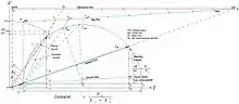
دیاگرام دایرهای موتور القایی
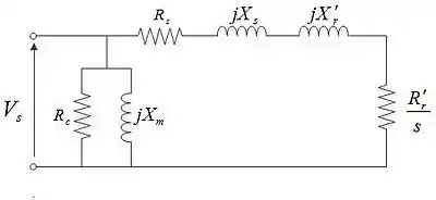
مدار معادل موتور القایی
منابع
- Behrend, B.A. (1921). The Induction Motor and Other Alternating Current Motors, their Theory and Principles of Design. McGraw-Hill. p. ix. Retrieved 4 January 2013.
- Heyland, A. (1894). "A Graphical Method for the Prediction of Power Transformers and Polyphase Motors)". pp. 561–564. Retrieved 4 January 2013.
- Terman, Frederick Emmons; Freedman, Cecil Louis; Lenzen, Theodore Louis; Rogers, Kenneth Alfred (Jan 1930). "The General Circle Diagram of Electrical Machinery". 49. American Institute of Electrical Engineers, Transactions of the.
- S.K.Bhattacharya. Electrical Machines (2008 ed.). Tata McGraw-Hill Education. p. 359. ISBN 0-07-066921-X.
- Heyland, Alexander (1906). A Graphical Treatment of the Induction Motor. G.H. Rowe, R.E. Hellmund (trans.). McGraw Publishing Company. Retrieved 10 January 2013.
- Phase to Phase BV (2006). "The Asynchronous Motor Model" (PDF). pp. 5–6. Archived from the original (PDF) on 10 August 2014. Retrieved 10 January 2013.
This article is issued from Wikipedia. The text is licensed under Creative Commons - Attribution - Sharealike. Additional terms may apply for the media files.